Raspberry Pi Traffic Light Controller (TrafficPi)

Solution
The purpose of this project is to educate children about the STEM (Science, Technology, Engineering, and Mathematics) fields. Through the use of low cost devices and effective teaching, children are able to associate what they are learning with interactions with everyday items. For example, most future engineers are aware of the purpose of a traffic light, but most are not aware of a traffic lights' internal workings. This project is designed to educate future engineers about the impact that computers and computer programming has with society. This project targets the "T, E, and M" of "STEM" by using electronic circuits for controlling the lights, software for controlling the electronic circuits, and mathematical calculations for making timing decisions.
One of the goals of this project is to be able to teach the next generation of engineers about the programming, software versioning, and how valuable engineers and technologists are to society and the impact that they have. A game was developed to be combined with this project to teach about software versioning, how sometimes Software Developers don't get it right the first time, and the negative impact that can occur if they don't get it right the first time.
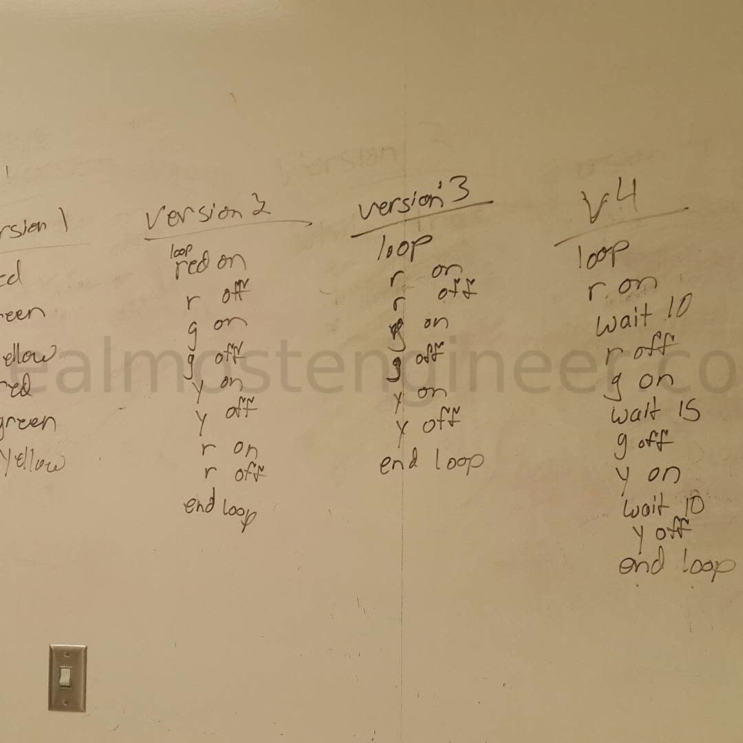
Below is the image of a group of future engineers working their way to developing the psuedocode for a normal traffic cycle. As shown in the first version, all of the lights turned on but never turned off. In the final version, they figured out that they had to turn on and turn off each light as well as include a delay in between each light change.

Technology
Below are the list of parts used for this project. You'll need to choose one of the mentioned options below depending on your budget. Using LEDs is cheaper than getting an actual traffic light.
- Raspiberry Pi
- Micro SD card (to run the OS and store project files)
- USB keyboard (mouse optional)
- HDMI display
- Breadboard Jumper Cables
- Breadboard (optional)
- .NET 5
- Raspberry Pi OS (has been tested with Raspberry Pi OS Jessie)
LED Option
Real Traffic Light Option
- Relay board(s) with at least 3 channels
- Traffic Light
Video Demonstration
Video demonstration of version 1.0 of the project is available to be watched at https://www.youtube.com/watch?v=lr_ZJNX0viM. This version of the demonstration of the traffic light working with an LCD screen connected.
Further discussion of the traffic light code can be watched at https://www.youtube.com/watch?v=ZyBnWOX3wGE.
Controller Software
The controller currently uses .NET 5. It is divided into two projects.
User Interface (UI) / Front End
The user interface is a .NET MVC application. When you select the program that you want to run from the application home page, the application then runs a linux command that runs the back end program. When the program is changed on the front end, the back end program is then terminated and the newly select program is started.
Relay Control / Back End
The back end of the application is a .NET Worker Service. The program modes are defined within this worker service. The worker service will continue running until it is terminated by the front end application or by a user via the command line or SSH.
Controller Hardware
Relays
Relays are used when devices of different voltages or amperages are being used together. One common example of this is relays that are used to control headlights on a car. The switch inside the vehicle has a lower amperage and is considered to be a "signal wire". When the switch is turned on, a relay is closed which then connects a different circuit to turn on and off the headlights.
In the Traffic Pi project, relays are used in a similar manner. The Raspberry Pi outputs 3.3VDC from the GPIO pins. Those pins are connected to a relay board. The relay board is also connected to a 120VAC which is needed by each of the signals. When the Pi sends an "on" signal to the relay board, the relay activates, thus sending 120VAC from the source (in this case a wall outlet) to the signal and then corresponding signal then turns on.
Wiring
The color of each wire always denotes its purpose. When using different color wires, you don't need to have a tag on each wire. Instead, you create a service manual or other documentation that lists the purpose of each wire based on its color.
For example, if you look a wiring harness on a car, you will notice that it has a number of wires that are bundled together. Each of those wires has a purpose. The vehicle manufacturers create a document, often referred to as a service manual, that lists each of the colors of the wire in the harness and their purpose.
With an AC circuit, there are commonly 3 wires. Black, white, and bare copper or green. Black wire in AC circuit represents the "hot" or supply voltage. White wire in AC Circuit represents the neutral. Green or bare copper wire in AC Circuit represents the ground.
With a DC Circuit, there are two wires. Red and black. Red wire in DC circuit represents the positive. This is the voltage that comes from the power source. Black wire in DC circuits represents the negative. This is the voltage that goes back to the power source.
AC vs DC
The current in an AC system alternates between the hot and neutral wires. The frequency at which this occurs varies. In North America (including the United States), the alternation takes place at 60 Hertz (Hz) or 60 times per second. In other parts of the world, this alternation takes place at 50 Hz per second. AC circuits are commonly used for items that require a lot of power to operate. These include large motors, like the ones used in AC refrigeration and industrial machines.
DC circuits are commonly used for battery powered systems, electronics, and other devices that do not require a lot of power to operate. If a device, such as a cell phone or streaming player, has a "power brick", then that device runs on DC power. The power brick converts the AC power to DC power and at the same time reduces the voltage to what the device needs.
Acknowledgements
- LCD Display code for controlling the LCD display were provided from https://github.com/the-raspberry-pi-guy/lcd.
- Attempts to replicate the Traffic Light Simulation created by Samuel Vidal seen at https://www.youtube.com/watch?v=xqZRDtX64UA influenced this project.
- Wifi AP configuration steps provided by https://pimylifeup.com/raspberry-pi-wireless-access-point/
Frequently Asked Questions (FAQs)
Where did you get the traffic light from?
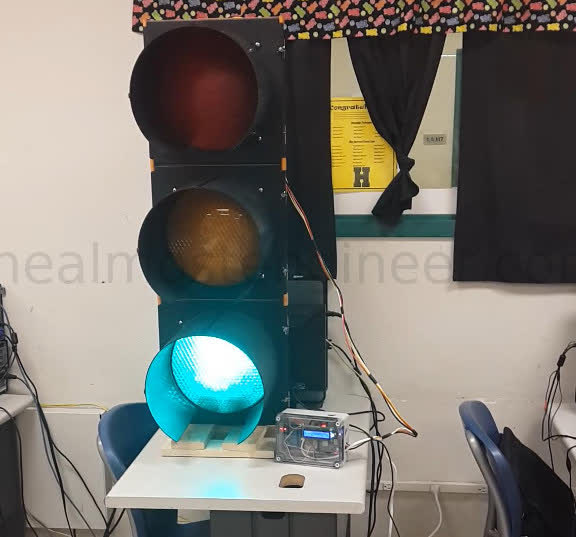
Ebay. Found a seller that own a salvage company that was selling it in 2018. The item that he had listed, included a controller, but the controller only had like 5 programs. I opted to get the light without the controller as I was going to build my own using the Raspberry Pi.
Will you share the source code for the application?
The source code for this project is available on GitHub at https://github.com/almostengr/trafficpi.
Is the traffic light heavy?
This one is made from plastic and weighs 25 pounds. Metal traffic lights weigh between 50 and 75 pounds.
How big is the traffic light?
Traffic lights come in two common sizes, 12 inch (30.48 centimeters) and 8 inch (20.32 centimeters). This is a 12 inch traffic light. It is about 14 inches wide and about 38 inches tall (with the base attached).
Traffic Control Classroom Activity
Objective
Programmers will have to come up with code to control the traffic lights and not cause an accident. While doing so, they learn programming concepts and how mistakes in their programs, can impact others significantly.
People Needed
- 1 volunteer as Traffic Light 1
- 1 volunteer as Traffic Light 2
- 1+ volunteers as programmers
- 3+ volunteers as vehicles
Placement of People

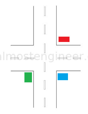
- Blue is programmers (control box). Audience should positioned so that they see both traffic lights.
- Red is Traffic Light 1
- Green is Traffic Light 2
Goals and Instructions
- Programmers are to come up with the code to control the traffic lights.
- Vehicles will go through one light and circle back around to the other light.
- Each mistake (or traffic collision) that they make means that they take the previous version of code and make corrections in the next version.
- To make this more challenging, programmers can be fired (and replaced with new programmers) if they make too many mistakes (or cause too many collisions).
- Ideally use a chalkboard or dry erase board for this so that the versioning differences can be seen.
- If running out of board space, previous versions can be erased. Do not erase the very first version. Once completed, this will allow a full comparison and what was done between the first and final version.
- Instructor will be “the internet”. If the programmers get stuck, they can ask the internet the question that they have.
- To make this more challenging, limit the number of questions that can be asked.
- Traffic lights will perform one action per command.
- To make this more challenging, “Light on” and “Light off” can be two separate commands.
Technical Information
The sections below this one, get into the technical details of the project. Those that are interested in setting up their own traffic light with a Raspberry Pi using the code that I have built, can follow the instructions below.
Installation and Setup
Install Raspberry Pi Operating System (OS)
You will need to install Raspberry Pi OS on your SD. Once you have completed this install, Then you can insert the SD card into the Raspberry Pi and power it on.
To install Raspberry Pi OS using Ubuntu, I made a video tutorial which you can watch at https://www.youtube.com/watch?v=Wy1_MWWlkNI.
Pin Setup
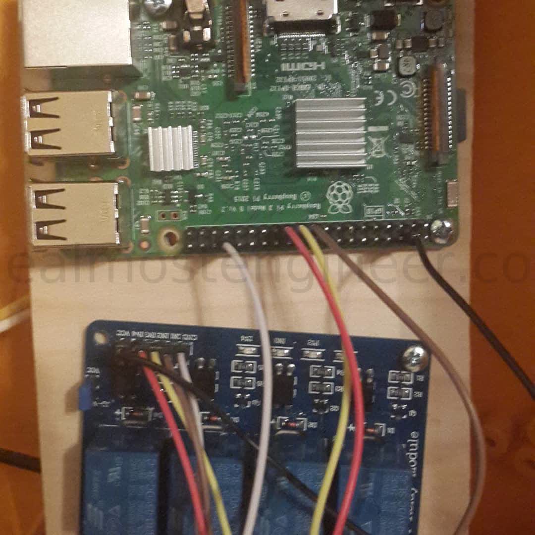
Below is the mapping for the connections to the Raspberry Pi. The Pin numbers listed are the physical pin numbers on the board, not the GPIO pin numbers. If you are not using a relay board, the connections can be made directly to a breadboard with LEDs connected.
| Pi Pin (Board) | GPIO | Device Connection |
|---|---|---|
| 04 | -- | Relay Board VCC (+5V) |
| 19 | 11 | Red Signal |
| 21 | 09 | Yellow Signal |
| 23 | 10 | Green Signal |
| 34 | -- | Relay Board GND |
| 15 | 22 | Button (Car Sensor) |
Visual of Pin Connections to Relay Board

System Service
To set up the application as a service, run the below commands. If you see error messages when running the commands, you may need to run them with "sudo" privileges. See the System Service page for details on how to add or remove the application as a system service.
Create System Service
sudo cp almostengrtrafficpiweb.service /lib/systemd/system
sudo systemctl daemon-reload
sudo systemctl enable almostengrtrafficpiweb.service
sudo systemctl start almostengrtrafficpiweb.service
sudo systemctl status almostengrtrafficpiweb.service
Run App On Pi
To run the applicatoin via the command line (not using the system service), then you can run the commands below.
cd trafficpi
./Almostengr.TrafficPi.Web
To exit the application after running it via command line, press Ctrl+C.
Uninstall Traffic Pi
Remove System Service
To remove the application as a system service, run each of the commands below.
sudo systemctl disable almostengrtrafficpiweb.service
sudo systemctl stop almostengrtrafficpiweb.service
sudo systemctl status almostengrtrafficpiweb.service
sudo rm /lib/systemd/system/almostengrtrafficpiweb.service
After running all of the commands above, then reboot the system.
Application Files
To remove the application files, you can remove the entire trafficpi directory.
rm -rf trafficpi
Troubleshooting
System Service Output / Log
To see the logged output from the system service, run the command:
journalctl -u almostengrtrafficpiweb.service -b
or
journalctl -u almostengrtrafficpiweb.service -b -f
If an error occurs in the application, the exception message will show here.